
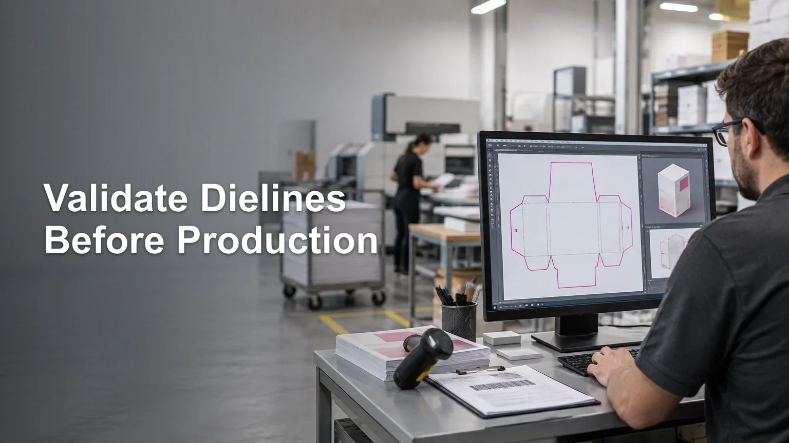
TLDR
A reliable dieline cut path preflight does not merely confirm that a line is visible. It verifies that the PDF is printable, identifies the intended finishing data, checks that the contour matches the ordered product, and routes the result to pass, hold, or human review. Automatic corrections should be limited to approved, deterministic changes. Never invent a missing custom contour or assume that a visually plausible line is safe for production.
The central question is whether the file contains an unambiguous, machine-usable finishing instruction. A dieline can look correct on screen yet be built as raster artwork, mapped to the wrong separation, hidden in optional content, duplicated, open, or unrelated to the product ordered. Those conditions can survive a casual visual check and still produce a failed cut, unwanted printed line, or incorrect shape.
Define the condition that must be true
Before configuring checks, define the acceptable file condition for each product. A production-ready file should be a readable PDF that meets the shop’s print requirements and contains finishing data that can be identified without guesswork. The contour must also be valid for the SKU, material, dimensions, and finishing method attached to the job.
That last requirement matters because there is no universal cut-path recipe. Acceptable bleed, contour offset, minimum radius, path complexity, line appearance, and cutter tolerance depend on the product and equipment. Preflight rules should therefore reference a product profile rather than one shop-wide idea of what a cut contour ought to look like.
The product profile should define at least the expected finished size, permitted page count, recognized technical-ink identifiers, expected path count, allowed contour types, bleed requirement, and destination finishing process. It should also state whether a rectangular contour may be derived from a page box or whether an explicit custom path is mandatory.
Dieline versus cut path
A dieline is the broader structural guide used to design a printed piece. Depending on the product, it may show cuts, folds, scores, glue areas, safe zones, perforations, or panel boundaries. It helps the designer place artwork correctly.
A cut path is the specific vector instruction intended for a cutting or converting operation. It needs to be isolated and mapped to a recognized production role. A single dieline can therefore contain several technical elements, while only some of them should reach the cutter.
This distinction prevents a common routing error: treating every nonprinting guide as a cut contour. A fold line, dimensions annotation, safe-area guide, and perimeter cut can all look similar in a design file. Production must identify what each object means, not infer its purpose from appearance alone.
Layer 1: Establish PDF and print readiness
Start by checking the PDF as a print file. Adobe describes Acrobat Preflight as profile-driven inspection against defined values, with checks covering areas such as color, fonts, transparency, image resolution, ink coverage, and PDF-version compatibility. Defined fixes can also be applied in some workflows. Adobe’s overview of profile-based PDF preflight explains this inspection model.
The base profile should examine PDF integrity, page count, required fonts, image quality, transparency behavior, color spaces, separations, and any restrictions imposed by the destination workflow. A cut path is not useful if the associated print file is corrupt, missing content, or incompatible with production.
Inspect the MediaBox, CropBox, TrimBox, and BleedBox as well. Adobe identifies page boxes as relevant to page positioning, printer marks, and imposition. Do not merely check whether the boxes exist; compare their dimensions and relationships with the ordered product. A correct TrimBox for a rectangular label does not prove that an irregular custom contour is correct.
PDF/X-4 can be a useful exchange requirement because it supports color-managed CMYK, gray, RGB, spot-color data, transparency, and optional content. It standardizes an exchange condition, however, not the intent or manufacturability of a product-specific contour. A file can conform to PDF/X-4 and still contain the wrong cut shape, an unrecognized technical ink, or no usable contour at all. ISO’s PDF/X-4 standard overview describes the scope of the format.
Layer 2: Identify the finishing data
The next stage searches for objects that the workflow recognizes as finishing instructions. A common implementation uses a vector path assigned to a configured spot-color separation. The name is not universal: the workflow must maintain an approved list of names, aliases, capitalization rules, and any permitted wildcard patterns.
Esko documents workflows that recognize configured cut-path ink names and warns that their configured order can determine which recognized ink is selected. That means detection should return more than a yes-or-no answer. It should record which identifier matched, where it appeared, how many candidate paths were found, and whether another technical ink could compete for the same role.
For packaging and label workflows, ISO 19593-1 provides a standardized mechanism for associating PDF objects and metadata with processing steps such as cutting and folding. This allows finishing intent to be represented more explicitly than with an ad hoc layer or spot-color name alone. ISO 19593-1 for PDF processing steps is the relevant published standard.
A practical intake profile may support both methods: standardized processing-step information when present and controlled local spot-color conventions for other incoming files. Detection should also inspect optional content and object structure, because a contour that is visible in one application may be hidden or omitted under another viewing or output state.
Do not rely on Output Preview as conclusive proof. Adobe notes that hidden layers are not included in its onscreen Output Preview and that overprint simulation is an approximation whose result can vary with the printer, RIP, and output settings. Preview is useful for diagnosis, but object-level inspection and a controlled downstream test are stronger evidence.
Layer 3: Validate the contour against the job
Once a candidate contour is found, compare it with the product definition and order data. This is where generic PDF inspection becomes production-specific dieline cut path preflight.
- Confirm that the candidate is a vector path rather than a raster line or decorative artwork.
- Verify that its identifier maps to the required finishing operation, not merely to a recognized technical color.
- Check whether the workflow expects one closed perimeter, multiple closed shapes, or a combination of cuts and other processing steps.
- Compare the contour’s bounds and orientation with the ordered finished dimensions and page boxes.
- Measure the artwork-to-contour bleed relationship using the SKU’s configured requirement.
- Detect open paths, duplicate paths, overlapping segments, unintended compound paths, and contours outside the permitted production area.
- Check whether multiple technical inks represent valid separate operations or an unresolved conflict.
- Confirm that the selected material and finishing device support the requested contour type and complexity.
These checks should produce explicit findings. “Cut path found” is too weak because it says nothing about whether that path is closed, unique, correctly sized, or mapped to the proper operation.
Choose pass, hold, or review rules
A good decision policy separates objective conditions from judgments about intent. Automation should be decisive where the system has enough information and conservative where it does not.
| Outcome | Use it when | Example |
|---|---|---|
| Automatic pass | Every required condition matches an approved product profile with no conflicting finishing data. | One recognized closed contour is present, its bounds match the SKU tolerance, required bleed exists, and no duplicate technical path is detected. |
| Automatic hold | An objective production requirement is missing or violated. | The PDF is unreadable, no mandatory custom contour exists, the path is open, or the detected contour uses an unmapped technical ink. |
| Human review | The file is structurally usable but intent or manufacturability remains ambiguous. | Two candidate contours are present, a fold line may have been classified as a cut, or an unusual shape is technically valid but outside the normal product profile. |
The review destination should match the uncertainty. An operator can resolve a known naming alias or confirm a production mapping. A designer should address geometry and artwork relationships. The customer should approve a change when the intended finished shape cannot be established from the submitted file and order data.
Workflow systems can route these outcomes independently. Esko, for example, documents preflight task outputs for OK, warning, error, and task failure states. The useful principle is platform-independent: convert findings into machine-readable states rather than burying them in a report nobody reads.
Keep automatic fixes bounded
An automatic fix should be deterministic, approved, reversible, and recorded. Suitable candidates might include normalizing an approved alias to the shop’s canonical technical-ink name or changing a recognized technical object to the configured nonprinting treatment. Even then, preserve the submitted file and record exactly what changed.
Do not silently redraw an irregular contour, choose between competing shapes, close a path when the intended connection is unclear, or replace missing finishing data with a guessed outline. Those actions change product intent rather than normalize file structure.
Some systems can generate a cut path from a TrimBox or stop with an error when no recognized cut ink is found. TrimBox-derived creation can be reasonable for a tightly controlled rectangular SKU whose rules expressly allow it. It is not a safe general replacement for a missing custom contour.
Move approved data into production without losing control
After approval, retain the original upload and create a controlled production derivative if normalization or separation is required. This supports the same controlled-file principle used in organizing print-on-demand artwork files before scaling fulfillment: production should receive an identified approved version, not whichever file happens to be easiest to find.
The handoff should direct each class of data to its proper destination. Print-intended artwork goes to the print and RIP workflow. Approved contour geometry goes to nesting, imposition, or cutting as required. Other technical elements, such as folds or scores, remain associated with their own processing steps rather than being flattened into ordinary print artwork.
ISO processing-step guidance describes this separation conceptually: all graphics may be available for proofing or viewing, print-intended objects are used for final printing, and relevant processing-step objects are used during finishing. The standard also addresses interactions between processing objects and ordinary graphics, including the risk of cut-related objects knocking out regular print content.
Add a first-off or downstream verification checkpoint for new profiles, changed equipment mappings, and unusual jobs. Preflight proves that the PDF met configured rules; it does not prove that every RIP, imposition template, or cutter interpreted the data as intended. This checkpoint can sit within a broader system of quality control checkpoints that reduce reprints.
Retain a traceable preflight record
The job record should preserve the original file identifier, approved derivative identifier, product profile, preflight profile and version, detected technical objects, findings, automatic corrections, report, reviewer decision, timestamp, and any human override. It should also connect the approved PDF with downstream nesting, RIP, and finishing output identifiers.
This is practical evidence when a job fails. It lets the team determine whether the problem entered with the customer file, arose during normalization, came from an incorrect product mapping, or appeared after the approved handoff. callas pdfToolbox documents preflight outputs that can include a processed PDF, report, status information, and error details, illustrating how those artifacts can travel together.
The production-ready rule
Treat the cut path as production data, not as a colored line that happens to look right. Define acceptance by product, inspect the PDF first, detect finishing data using controlled identifiers or processing-step metadata, validate geometry against the order, and route uncertainty instead of guessing.
The best next step is to choose one representative SKU and write its acceptance profile in measurable terms. Run known-good, known-bad, and ambiguous files through it. Once the resulting pass, hold, and review decisions match operator judgment, connect those states to production routing and preserve the report with every job.
References
- Analyzing documents with the Preflight tool (Adobe Acrobat Pro) | Adobe Acrobat
- Print production tools overview in Acrobat Pro | Adobe Acrobat
- ISO 15930-7:2010 – Graphic technology — Prepress digital data exchange using PDF — Part 7: Complete exchange of printing data (PDF/X-4) and partial exchange of printing data with external profile reference (PDF/X-4p) using PDF 1.6
- Create Tiles (Classic)
- ISO 19593-1 – Graphic technology — Use of PDF to associate processing steps and content data — Part 1: Processing steps for packaging and labels
- ISO/DIS 19593-1(en), Graphic technology ? Use of PDF to associate processing steps and content data ? Part 1: Processing steps for packaging and labels
- Previewing output (Adobe Acrobat Pro) | Adobe Acrobat
- Preflight with PitStop Task
- pdfToolbox Rest API – Operation: Preflight | callas pdfToolbox | Step by step – Learn how to use callas products